
As industrial facilities continue to imp
Selecting suitable cooling tower fill me
How Cooling Tower Fill Design Affects En
During a cooling tower inspection, engineers sometimes discover an interesting situation: the Cooling Tower Fill inside the same tower does not always age at the same speed.
Some sections may still look acceptable, while other areas show more scaling, deformation, dirt accumulation or material aging.
A common reason is the different operating environment experienced by different fill locations.
The fill blocks near the air inlet are often exposed to conditions that are different from the internal sections of the tower.
Understanding this difference can help engineers make better maintenance decisions and avoid replacing or inspecting the wrong areas.
Many people imagine the fill inside a cooling tower as one complete cooling surface working under identical conditions.
In reality, every section of the tower has its own local environment.
The conditions can be affected by:
Because of these differences, some areas of the Cooling Tower Media may experience faster aging than others.
The air inlet is the first point where outside air enters the cooling tower.
Depending on the installation environment, the incoming air may contain:
Over time, these materials can accumulate on the surfaces of the fill near the air inlet.
This is especially important for towers installed near:
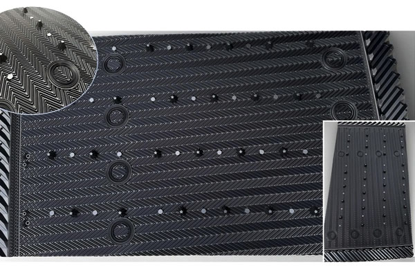
Modern Film Fill relies on open channels to allow proper air and water movement.
The corrugated structure creates repeated contact surfaces where water spreads and exchanges heat with air.
When external contamination accumulates near the air inlet side, several problems may occur:
Deposits and debris can partially block the open channels inside the fill.
This increases airflow resistance and may reduce the effective air volume passing through the tower.
Blocked areas may prevent water from spreading evenly across the fill surface.
Some sections may become over-wetted while others receive less water.
Long-term deposits can create additional weight and mechanical stress on the fill sheets.
This may accelerate deformation in some areas.
In a counterflow tower, air enters from the lower section and moves upward through the fill.
The lower fill area near the air inlet experiences the first contact with incoming air.
For replacement projects, a product such as 750/930mm Cross-flow/Counter-flow Fill should be evaluated not only by its dimensions, but also by the actual airflow and water-distribution conditions inside the tower.
In crossflow towers, air enters horizontally through the fill.
The first rows of crossflow fill are directly exposed to incoming air conditions.
For example, 1010mm × 2500mm Cross Flow Fill for Cooling Tower Applications represents a specific dimensional configuration that still needs to be matched with the actual tower structure and airflow arrangement.
Therefore, inspection should pay special attention to the air-entry side of the fill.
During routine maintenance, many teams inspect only the visible top area of the fill.
However, the first air-contact area may provide more useful information about tower conditions.
Signs to check include:
A small inspection window can sometimes reveal more than checking only the easiest accessible area.
Air-inlet-side deterioration should also be considered together with the physical arrangement of the fill blocks.
If the replacement blocks do not match the available installation space, excessive gaps or on-site cutting may create irregular airflow paths.
For replacement projects involving different tower dimensions, configurations such as 870mm Width Cross-flow Fill can be considered when the tower requires a specific fill width rather than a generic standard block.
The important point is not simply choosing a wider or narrower fill. The dimensions should match the existing support arrangement and maintain the intended air and water flow through the tower.
Fill dimensions should always be considered together with the actual tower geometry.
A larger fill section may be suitable for one tower but completely unsuitable for another if the internal support arrangement, access space or airflow path is different.
For example, 1520 Width Cooling Tower Fill may be appropriate for a particular installation where the available space and tower configuration support that width.
The correct approach is therefore to confirm the actual fill dimensions before ordering replacement media instead of selecting a product based only on its nominal width.
Different plastic materials may behave differently under long-term operating conditions.
The correct material selection depends on:
A fill material suitable for one location may not provide the same long-term result in another environment.
However, material selection should be evaluated together with fill structure, operating conditions and the actual source of deterioration rather than treating material type as the only cause of aging.
Not every tower requires complete fill replacement immediately.
If only specific areas show accelerated aging, partial replacement may be considered after proper inspection.
However, engineers should first determine why the damage occurred.
If the cause is still present, new fill installed in the same location may experience the same problem again.
When air inlet areas show unusual fill deterioration, inspect the surrounding installation conditions as well.
Important items include:
A damaged or uneven support structure can cause local deformation, while poor water distribution can create areas with excessive wetting or insufficient wetting.
This is why the condition of the fill should not be judged separately from the conditions around it.
For large industrial towers, a useful inspection method is to divide the fill area into zones.
Check contamination, blockage and material condition.
Compare structure and wetting condition with the air inlet area.
Look for differences in scaling, airflow and water distribution.
Comparing different zones provides more accurate information than checking only one location.
For a useful maintenance record, photograph representative areas from different positions inside the tower.
Record the location of each photograph and note whether the area shows:
Comparing these records during future shutdowns can help identify whether deterioration is progressing from the air inlet toward the internal fill sections or remaining localized.
Cooling Tower Fill does not age equally throughout the tower.
Areas near the air inlet often experience more contamination, different airflow conditions and greater environmental exposure.
When evaluating fill condition, engineers should look for location differences instead of judging the entire tower based on one section.
Fill dimensions should also be considered carefully during replacement because an incorrectly sized block can create installation problems and unwanted airflow paths.
A detailed understanding of how each area operates can help determine whether the correct solution is cleaning, partial replacement or complete Cooling Tower Fill replacement.
The goal is not simply to install new fill. The goal is to make sure the replacement fill matches the tower's actual geometry, airflow direction, water distribution and operating environment.
Industry trends and cooling tower fill media insights for global customers.
As industrial facilities continue to improve energy efficiency and equipment reliability, cooling to
Winter Operation: Cooling Tower Fill Challenges and Cold-Weather AdaptationsWhy Winter Changes the R
Connect with our team for cooling tower fill media details, project information, and technical assistance.
Chat on WhatsApp