
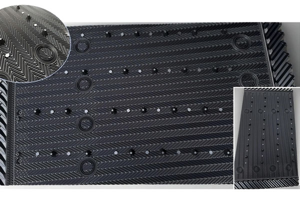
As industrial facilities continue to imp
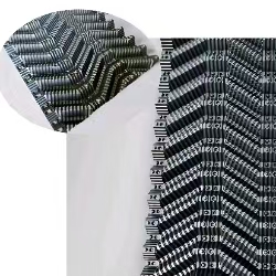
Selecting suitable cooling tower fill me
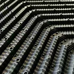
How Cooling Tower Fill Design Affects En
When a cooling tower starts using more fan power or the fan seems to be working harder than before, the first things people usually check are the motor, gearbox, fan blades and electrical system.
Those checks make sense, but there is another part of the tower that deserves attention: the Cooling Tower Fill.
Most engineers know that cooling tower fill provides the contact area between water and air. What is sometimes overlooked is that the fill is also part of the tower's air resistance.
That means a change inside the fill can affect not only heat transfer, but also how much effort the fan needs to move air through the tower.
This becomes particularly important as a cooling tower gets older. Deposits, biological growth, damaged sheets, collapsed channels or an unsuitable replacement fill can gradually increase airflow resistance.
The tower may still be cooling water, but it may be doing so at a higher energy cost.
Pressure drop is simply the loss of air pressure as air moves through the cooling tower components.
Every component in the air path contributes some resistance. Air inlet louvers create resistance. Cooling Tower Media creates resistance. Drift eliminators create resistance. Other internal structures also contribute to the total system resistance.
The fan has to overcome this resistance in order to move the required amount of air.
In a simplified way, the relationship can be viewed like this:
Total fan system resistance = inlet resistance + fill resistance + eliminator resistance + other tower losses
This is why Cooling Tower Fill cannot be selected only according to its theoretical heat transfer area.
The fill must also provide an acceptable balance between heat transfer and airflow resistance.
When comparing Film Fill products, it is tempting to focus on the largest available surface area.
That sounds logical. More surface area should mean more contact between air and water.
But there is a practical limit.
If the structure becomes too restrictive for the available fan capacity, the tower may not be able to move enough air through the fill.
At that point, the theoretical increase in surface area may not translate into better real-world cooling.
This is one of the reasons experienced cooling tower engineers look at both thermal performance and pressure drop.
In a film fill cooling tower, air travels through a network of relatively narrow passages created by the corrugated sheets.
These passages are part of what gives Film Fill its large effective contact area.
However, the same geometry creates resistance to airflow.
The actual resistance depends on several factors:
This means the pressure drop of a new fill and the pressure drop of the same fill after several years of operation may be very different.
One of the easiest ways for airflow resistance to increase is through fouling.
Scale, biological growth, dust, sludge and other deposits can gradually reduce the open passages inside the fill.
Imagine an air passage as a small tunnel.
If part of that tunnel becomes covered with deposits, the remaining opening becomes smaller.
The air still has to pass through.
As the available area decreases, resistance increases.
This is why a Cooling Tower Media inspection should not focus only on whether the fill is physically broken.
A fill block can be structurally intact while its airflow characteristics have changed significantly.
Mineral scale can be especially troublesome because it may form gradually.
At the beginning, the change may be almost impossible to notice from outside the tower.
Over time, however, deposits can narrow the channels and change the surface geometry.
The result can be a combination of lower effective heat transfer and higher airflow resistance.
If the fill creates more resistance than the fan system can comfortably overcome, several things may happen.
The exact result depends on the fan, drive system and tower design, so it is important not to assume that every pressure-drop problem produces the same symptom.
But the general engineering principle is simple: the fan and fill need to be considered as one air-moving system.
Counterflow towers move air upward through the Cooling Tower Fill while water moves downward.
This arrangement means that the fan must overcome the resistance created by the complete vertical airflow path.
For a replacement project, the selected 750/930mm Cross-flow/Counter-flow Fill should therefore be evaluated not only by its thermal characteristics but also by its compatibility with the tower's airflow capacity.
If the replacement fill has significantly different airflow characteristics from the original design, the fan operating point can change.
That is why replacing fill with a product that simply “looks similar” is not always a good engineering approach.
In a crossflow tower, air generally enters horizontally through the fill while water travels downward.
The airflow path and fill depth therefore need to be considered differently from a counterflow arrangement.
A Cross-flow Cooling Tower Fill (Double-wave Design) should be selected according to the actual tower design, not simply based on the name of the fill.
This is another area where “more fill” can create an unexpected problem.
Increasing fill height increases the distance that air must travel through the fill structure.
Under otherwise similar conditions, a deeper fill section can create greater resistance.
However, this does not mean that a deeper fill is bad.
The correct question is whether the additional heat transfer benefit is justified by the additional airflow resistance.
This is a system optimization problem, not a simple “higher is better” calculation.
Suppose an old tower originally used a relatively open fill design.
A retrofit supplier proposes a newer, more compact film fill with a higher theoretical surface area.
On paper, the new fill may look like an upgrade.
But if the tower fan was not designed for the additional resistance, the result may not be what the customer expected.
For older towers with unusual fill-bay dimensions, a product such as Multi-Specification Cross Flow Cooling Tower Fill can be evaluated together with the existing fill dimensions and fan operating conditions.
This is exactly why retrofit work should consider the existing fan curve and operating conditions.
Fill is not the only source of airflow resistance.
Air first has to enter the tower.
Damaged, blocked or heavily fouled Cooling Tower Air Inlet Louvers can alter the airflow before it reaches the fill.
If a tower is experiencing unusual airflow behaviour, inspecting the louvers is worthwhile before assuming that the fill is responsible.
At the upper section of the tower, air passes through the drift eliminators.
Heavily fouled or damaged Drift Eliminators can add additional resistance.
This is important when troubleshooting because a tower may have several small restrictions rather than one single major problem.
The combined effect can be significant.
If the fan seems to be working harder than before, I would start with operating data rather than immediately removing the fill.
Record fan speed, motor current and other available operating data.
Compare current airflow information with historical operating data if available.
Inspect for scaling, sludge, biological growth, deformation and blocked passages.
Inspect louvers and surrounding structures.
Look for deposits, deformation and blocked passages.
Look at hot-water temperature, cold-water temperature, ambient conditions and water flow.
This allows the engineer to determine whether the problem is mainly thermal, hydraulic, airflow-related or a combination.
Sometimes it can.
If the fill is structurally sound and the deposits are removable, cleaning may restore part of the original open area.
But cleaning has limits.
Heavily scaled or deformed fill may not return to its original geometry even after deposits are removed.
Aggressive cleaning can also damage plastic sheets if inappropriate pressure, chemicals or methods are used.
Cleaning should therefore be based on the condition and material of the fill rather than treated as a universal solution.
In applications where fouling is a major concern, an open splash structure may sometimes be worth evaluating.
Splash Grid Fill uses a different approach to water-air contact and can provide more open passages than many compact film structures.
That does not mean splash fill always produces lower airflow resistance or better overall performance. The actual design needs to be evaluated as a complete system.
Trend monitoring is particularly useful.
If fan operating conditions gradually change while the cooling load remains similar, it can be a sign that the air path deserves inspection.
Cooling Tower Fill is not only a heat transfer surface. It is also part of the tower's aerodynamic system.
The best fill is therefore not necessarily the one with the highest theoretical surface area.
A good design balances heat transfer, water distribution, airflow resistance, fouling risk, fan capacity and long-term maintenance.
When evaluating a new Cooling Tower Fill or planning a retrofit, always ask two questions:
How much cooling performance will the fill provide?
How much airflow resistance will the fan need to overcome?
Looking at both questions together is one of the easiest ways to avoid a retrofit that looks good on paper but performs poorly in the real cooling tower.
Industry trends and cooling tower fill media insights for global customers.
As industrial facilities continue to improve energy efficiency and equipment reliability, cooling to
Winter Operation: Cooling Tower Fill Challenges and Cold-Weather AdaptationsWhy Winter Changes the R
Connect with our team for cooling tower fill media details, project information, and technical assistance.
Chat on WhatsApp